Mouse Input Modifier · Open Hardware · Build it in an afternoon
MIM is open hardware — and that's the whole point. The device that reshapes your mouse input in real time is something you can hold, open up, and build yourself. No locked-down black box: the exact same firmware that ships in the finished Alpha units runs on a Teensy you solder at your own kitchen table. Start with a bare-bones board in about 25 minutes, or go all the way to a full build with dual displays and encoders in an aluminium enclosure. Three tiers, each one building on the last, and firmware flashing that works the same across all of them.
| Tier | Name | Soldering | What you get |
|---|---|---|---|
| Tier 1 | Bare Bones | ~25 min, basic skills | Fully functional, no enclosure |
| Tier 2 | Compact Build | ~40 min | Permanently soldered, reset button, stable |
| Tier 3 | Full Build | ~2 h | 2× TFT, 2× encoder, aluminium enclosure |
Goal: The fastest possible path to a working MIM — just a handful of solder joints. Perfect for a first taste before you commit to a fancier build.
| Part | Source | Note |
|---|---|---|
| Teensy 4.1 | SparkFun / DigiKey | SparkFun DEV-20360 |
| Micro-USB cable | any | Teensy → PC |
| USB-A socket on breakout board | AliExpress / Amazon | for mouse / keyboard / controller |
| 4× jumper wires (male–female) | any | 10–15 cm is enough |
| Soldering iron + solder | — | Basic equipment |
The Teensy 4.1 has five pads on its bottom side for the USB host connection. This is where you connect the mouse, keyboard, or controller.
Pad 2  →  +5V   (USB Pin 1)
Pad 3  →  D−    (USB Pin 2)
Pad 4  →  D+    (USB Pin 3)
Pad 5  →  GND   (USB Pin 4)
Pad 6  →  GND   (optional, can share with Pad 5)
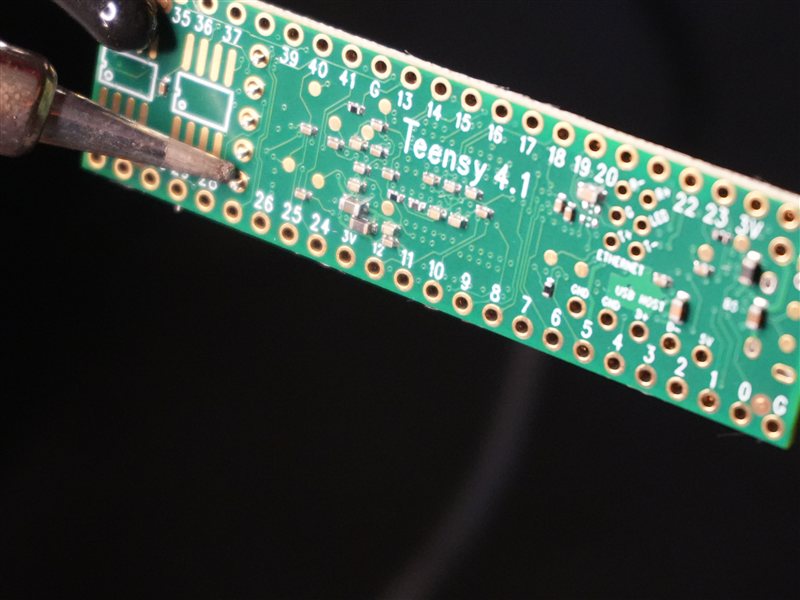
Teensy 4.1 — Bottom side with USB Host pads (Pads 2–6). Red = +5 V, White = D−, Green = D+, Black = GND.
MOUSE / KEYBOARD / CONTROLLER
        │
  USB-A Socket (Breakout)
  Pin 1 (+5V)  ──── Teensy bottom Pad 2
  Pin 2 (D−)   ──── Teensy bottom Pad 3
  Pin 3 (D+)   ──── Teensy bottom Pad 4
  Pin 4 (GND)  ──── Teensy bottom Pad 5
        │
     [Teensy 4.1]
        │
  Micro-USB (top)
        │
       PC
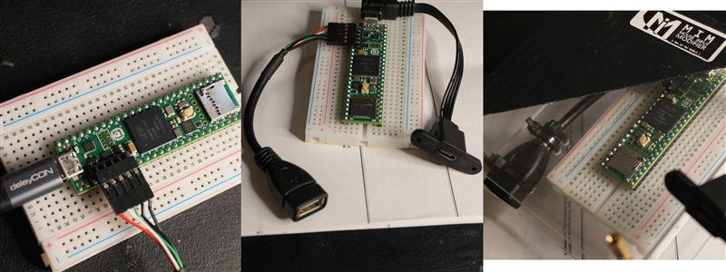
Bare Bones build — left: with deleyCON USB-A adapter and extension cable; center: with right-angle USB-A socket; right: mounted on breadboard with wiring.
The Bare Bones build fits into a compact aluminium enclosure — no additional soldering required, just cable management and a USB-C panel-mount adapter.
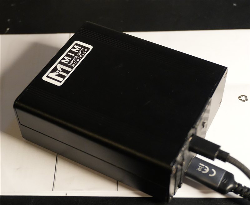
Completed Bare Bones build in aluminium enclosure with MIM label and USB-C cable.
For more complex builds, correct wiring according to the firmware implementation is essential. The diagram below shows the full connection overview for all supported configurations.
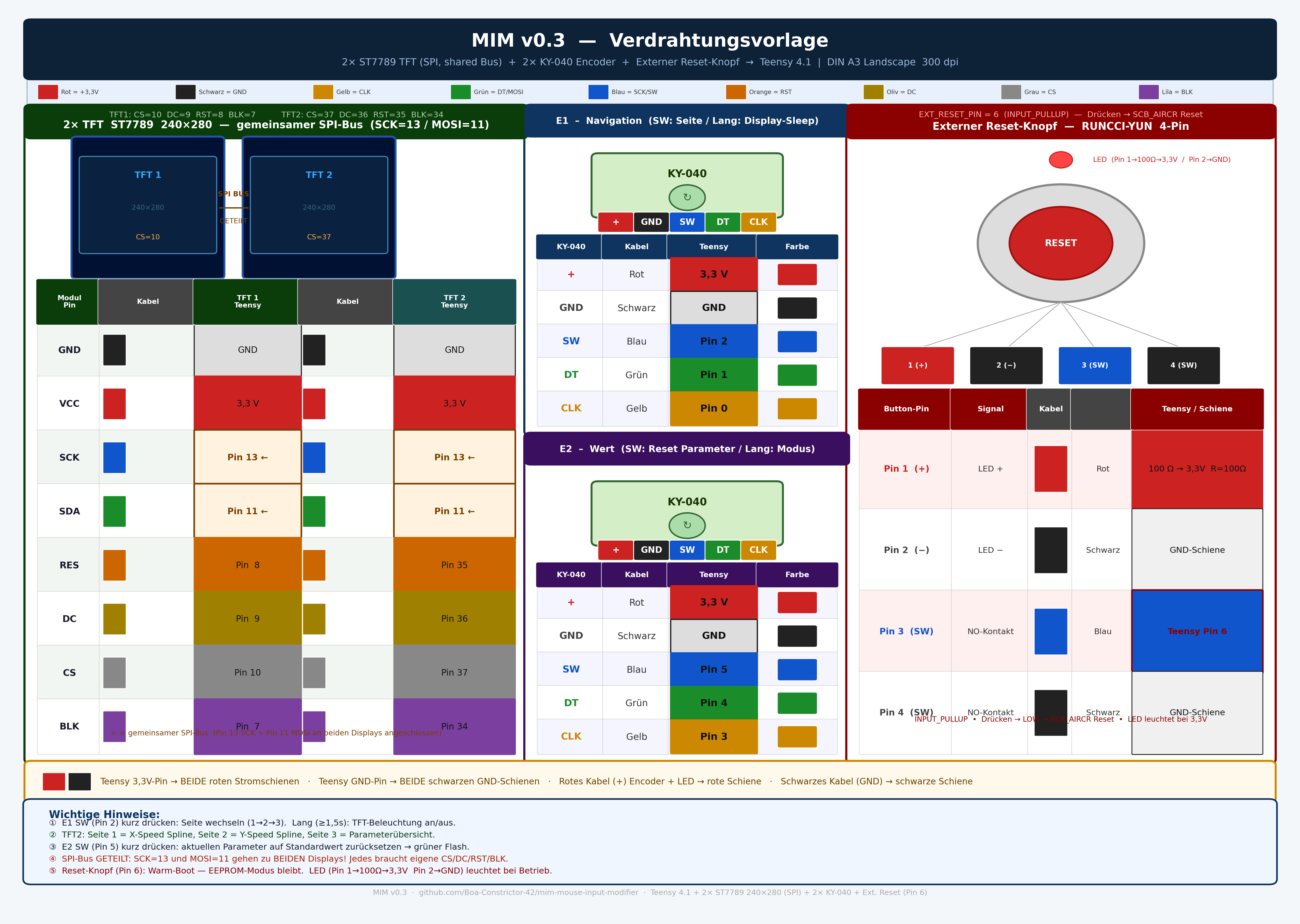
MIM Wiring Diagram v03 — Overview
Builds on Tier 1. This is the one you'll actually keep on your desk: permanently soldered on perfboard, with a proper reset button and buffer capacitors. Rock-solid even with high-resolution gaming mice (Beast X Pro, 4K polling) — set it up once and forget about it.
| Part | Value / Type | Source | Note |
|---|---|---|---|
| Perfboard | ~80 × 50 mm | AliExpress / Conrad | Teensy fits on 56-pin board |
| Buffer capacitor 1 | 1000 µF / 16 V, Low-ESR | Conrad / Reichelt | Electrolytic, on USB host VBUS/GND |
| Buffer capacitor 2 | 100 nF, MLCC | Conrad / Reichelt | Ceramic, parallel to electrolytic |
| Reset button | Momentary, illuminated | AliExpress | e.g. RUNCCI-YUN 16 mm |
| USB host cable | USB-A socket with pigtail | AliExpress | instead of breakout board |
| Wire | 4× 0.25 mm² | any | for USB host wiring |
High-resolution mice (2000Hz and more) can cause brief voltage drops on the VBUS line during enumeration, leading to connection drops. The capacitors buffer these spikes directly at the Teensy's host port.
Placement: both capacitors in parallel between Pad 2 (+5V) and Pad 5 (GND) on the bottom of the Teensy, as close to the pads as possible.
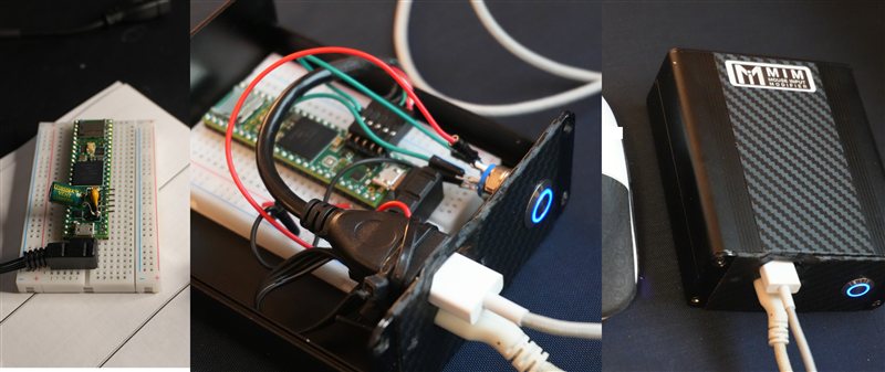
Left: Bare Bones build on breadboard. Center: Compact build with capacitors, USB-A socket, and illuminated reset button. Right: Finished build in compact enclosure.
The reset button provides direct access to the HalfKay bootloader — useful when the firmware has locked up or for a manual firmware update.
Connection: Program pad (top left on Teensy, labelled) → GND
[Button] ──── Program pad (Teensy front side, top left)
[Button] ──── GND
Builds on Tier 2. The full experience: dual TFT displays, two encoders, an aluminium enclosure and a panel-mounted USB-C socket. Tune your curves live on the device, no laptop needed. This is exactly the Alpha Edition build — the same unit you'd get if you ordered a finished one.
| Part | Type | Source | Note |
|---|---|---|---|
| TFT Display 1+2 | ST7789, 240×280, SPI | AliExpress | 2 pieces |
| Encoder 1+2 | KY-040 with button | AliExpress | 2 pieces |
| Enclosure | Hammond 1455KGYBK | Mouser / RS Components | 120 × 65 × 27 mm |
| End panels | ABS, matching Hammond 1455 | Hammond / Mouser | or 3D print |
| USB-C Panel-Mount | CF-V8RI, 90°, 10 cm | AliExpress | Micro-B Male → USB-C Female |
| Screws / standoffs | M2.5, assortment | Amazon | for perfboard mounting inside enclosure |
E1 (left)   — Navigation (select parameter)
E2 (right)  — Change value / mode toggle (LongPress)
Both encoders: CLK, DT, SW pins each to free digital pins on the Teensy.
Both displays share the SPI bus (MOSI, SCLK, common) but each has its own CS and DC pin.
Display 1: CS → Pin X, DC → Pin Y
Display 2: CS → Pin A, DC → Pin B
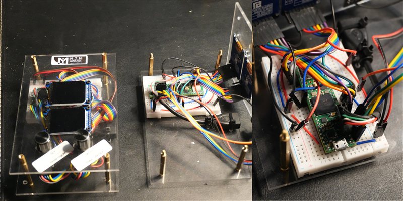
Full Build — interior view: perfboard mounted in enclosure slots, both TFTs installed, cable routing completed.
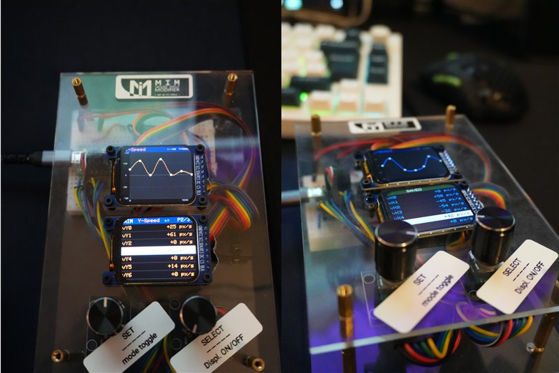
Full Build — both TFT displays active: speed curve (top) and Y-speed profile values (bottom). Left and right encoder for navigation and value adjustment.
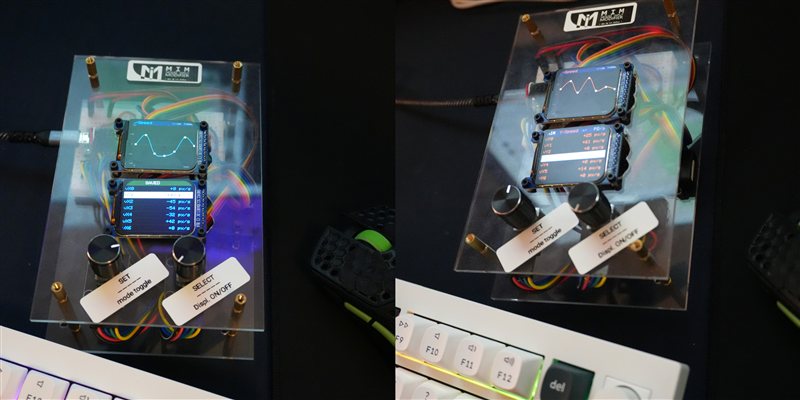
Full Build from above — both displays and encoders visible. Device connected and in use.
The same firmware runs on all three hardware tiers — no per-tier configuration needed.
.hex file.hex in Teensy Loader, connect the Teensy via Micro-USB, press the white button on the Teensy — it flashes automatically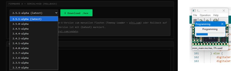
Teensy Loader with the MIM firmware .hex loaded — progress bar during flash.
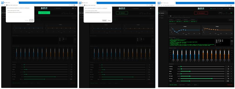
mim-control.com — left: port selection dialog; center: correct port selected; right: connected with full MIM interface, speed curves, and serial monitor active.
After the initial flash, updates can be installed directly from the browser.
.hex file is loadedAIM converts mouse input into joystick deflection (XInput output). CIM passes a connected controller through with correction applied. Both modes output XInput signals instead of standard HID.
These modes require Firmware C — a separate firmware image available on mim-control.com/dev-options under "Firmware C". Flash it the same way as Firmware A using Teensy Loader.
Note: mim-control.com does not work with Firmware C. Configuration requires external tools. To return to MIM / KIM, simply flash Firmware A again.
Questions, problems, preset sharing — all in the Discord:
And if you'd rather skip the build entirely: ask about a ready-to-use unit there too — same place, same friendly people.
Video build guide:
MIM · Mouse Input Modifier · github.com/boa-constrictor-42 · DIY Guide v1.0